DIESEL GENERATOR
Power Control Sale and Services, has been dealing in Diesel/Gas generators sales / parts / product support services since 2009 in Pakistan and have more than 100 customer base throughout Pakistan.
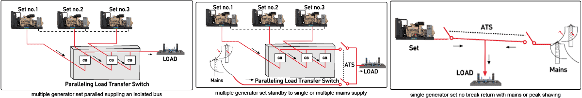
Auto Synchronizing and Load Sharing
We are actively engaged in supplying high performance DG Synchronization Panel which comes complete with Controlling & Protection Relays capable of synchronizing of more than one DG sets / with Mains & DG and with necessary protections. The offered product is precisely designed and manufactured by utilizing optimum quality raw material and sophisticated technology. Furthermore, we offer this DG Synchronization panel in various technical specifications at affordable prices.
PLC system has been designed to provide following salient features for DG sets ..
The system will come in operation after sensing of Grid Failure. The initiation of DG operation can be done in AUTO / MANUAL mode from Man-Machine-Interface to automatically control the start & stop of engines, depending on the predefined load & DG selection in the PLC.
In case DG engines do not start in the first cranking, two or more auto commands should be given with proper intervals. Even that if engine fails to start indication will appear on ManMachine-Interface.
At the time of power failure PLC will start engines as per LOAD requirement i.e. Running load is sufficient only for one engine when PLC will start only Master DG & in another case if Load requirement is for Three DG sets, PLC will start Master, Second & Third engine as per selection.
PLC will sense the Load running on Transformer in every 3 seconds to start the No. of DG sets as per the Load requirement.
In the case of Load management during “Power Available”. If Load exceeds more than the capacity of the Transformer then PLC will start Master Engine and close the breaker for the
same engine, or, as per Load requirement if two or more engines required. In this case Bus Coupler will be in open Position as per requirement of Single Line Diagram.
The facility of synchronization will be available in Auto mode. In normal circumstances the auto synchronization will work, however due to any reason auto synchronization fails, PLC will generate an audio visual alarm and initiate start command to next generator ready for operation. Before synchronization PLC system will monitor & control DG parameters like voltage, frequency & phase angle difference and when the parameters of main bus & DG will be in defined range, PLC system will connect the output of DG to main bus.
Sensing both active & reactive power will perform auto load sharing. The percentage loading of a particular DG will be fed by MMI. This feature is important when synchronization is done between new and old, or between DG’s of different ratings. New DG is normally has high loading factor than a old DG. PLC will allow only predefined loading to all the DG’s
Load management system is designed for auto start/ stop for the slave DG sets as per the load requirement i.e. in case of running DG sets being over load (more than 80%) then PLC will start the next DG sets after a pre-defined time delay. After starting the DG set PLC will take care the synchronization and proper load sharing as per DG rating. In case running DG sets being under load (less than 60%) then PLC will stop the one DG set after transferring the load on another running DG sets.
There is another provision to “By Pass” Load management system. If you want to start/stop slave engines Manually through SCADA or MMI with auto synchronization. In this case DG start/stop can be done through SCADA or MMI only and close breaker after achieving the required parameters of Synchronization.
A. Engine:
Over speed fault
Low lube oil pressure
Water temperature High
Emergency Stop
B. Electrical:
Under voltage
Over Voltage
System Features
The system is designed run in AUTO as well as in MANUAL mode. In auto mode the system will run automatically with predefined sequence and in manual mode all the operation will be done as per the sequence will be defined by operator.
DG’s will be started & stopped automatically as per the load requirement on the main bus.
Selection of DG’s for DG start stop automatically on sudden load requirement.
Automatic synchronization of DG sets in Auto mode
Active & reactive Load sharing of each DG set
Automatic selection of Next DG as master after stopping / tripping of master DG to close NGR circuit.
Monitoring of electrical parameter of each DG, voltage, frequency, reactive load, active load, energy produced, voltage error (%), frequency error and phase angle error etc.
Status & control of outgoing breakers
Back up protection electrical / mechanical by time delayed tripping of Dg sets.
Reverse power; reverse KVAR, under voltage, over voltage, under frequency, over frequency, over current, low lube of oil pressure, high cooling water pump, over speed etc.
Data acquisition system will be incorporated with the system for the purpose of recording & display of all important & critical parameters of the engine, alternator & system as such in totality. Operation of the system will also be through operator interface with graphics screen into PC Pentium computer.
“B” checks alarm after each DG complete 300 hours of running for proper maintenance.
Tripping of non-critical loads in the plant in case of under frequency of bus both in isolation as well as synchronized mode.
Control of all auxiliary drive of DG sets will start stop automatically with proper interlocks as per safety considerations.
PLC system will have provision to test the DG in auto mode without closing the breaker to do the routine electrical / mechanical testing of DG sets without interruption of power generation.
Master DG
PLC system will monitor the Grid Failure signal through under voltage relay. As soon as GRID supply fails, PLC will start master DG set and after getting the proper voltage and frequency, PLC will close the first neutral contactor and then DG incomer MCCB automatically after ensuring the T/F ACB is in trip condition. When GRID supply gets restored PLC will issue an audio-visual alarm after a pre-defined time delay to operator attention. Change over will be done automatically by PLC with proper interlock i.e. PLC will first trip the DG sets incomer ACB/ MCCB then transformer ACB shall be switched-on automatically.
Slave DG
Slave DG, start/ stop will be done as per Load Management system. After starting the slave DG set, PLC will compare the Voltage, Frequency and Phase angle between Synchronizing bus & reference bus. After matching these parameters PLC will close the slave DG ACB/ MCCB automatically. Load sharing will be also done by PLC automatically
Load Management System
If Single DG is running on load and total load is more than 80% of running DG then PLC will start the 2nd DG after a pre-defined time delay. Synchronization and load sharing shall be done by PLC automatically. If two DG`s are running on load and total load is more than 80% of running DG`s then PLC will start the 3rd DG set after a pre-defined time delay. Synchronization and load sharing shall be done by PLC automatically. If N DG set are running on load and total load is less than 70% of N-1 DG set then PLC will trip the ACB/MCCB of last DG automatically after a pre-defined time delay. Engine will stop after 3 minutes idle running in auto mode. Above process shall continue while running the system in auto mode to achieve the maximum efficiency of DG set.
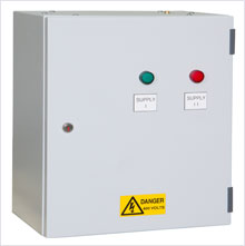
AUTOMATIC CHANGEOVER ON LOAD SWITCH PANELS
In the event of a power outage, our changeover panels are designed to transfer the supply to an emergency backup supply, either manually or automatically depending on the need of the application. Manufactured from 16A up to and including 4000A. If you require more information, submit an enquiry and one of our design engineers will contact you shortly. |
 |
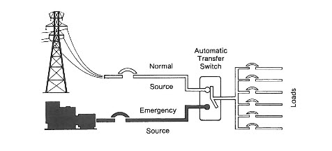
The control panel system of a transfer switch is what makes the unit automatic in nature. Manual transfer switches are operated by onsite personnel and are used in situations where the load is not of an emergency nature requiring immediate restoration of the power supply. With an automatic transfer switch, power failures are detected immediately and the transition from utility power to generator power is seamless. The control panel’s job is to detect a power failure and initiate procedures to start the new or used generator’s engine. Once the new or used generator reaches the correct voltage and frequency (for the end use application) the control system signals the switch to transfer from the normal source of power to the generator. The engineering behind an automatic transfer switch is quite complex as time delays and other components play a pivotal role in obtaining instantaneous backup power. |
|
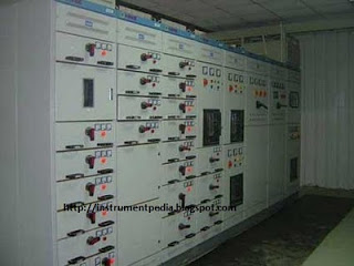
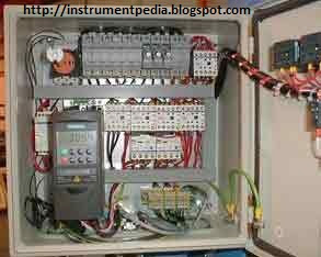
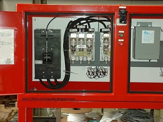
ELECTRICAL CONTROL PANELS
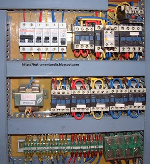
Control Panel Components
| Control Panels |
|
|
|
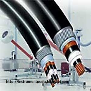
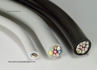
Cables |
|
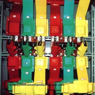
Bas Bar |
|
 |
 |
 |
|
 |
 |
|
 |
|
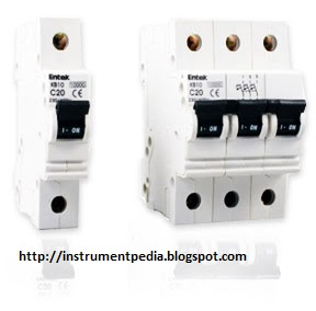
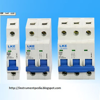
| MCB |
MCCB
|
ELCB
|
|
Incommer
|
|
|
|
 |
|
 |
|
 |
|
|
|
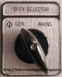
| Selector Switch |
|
|
|
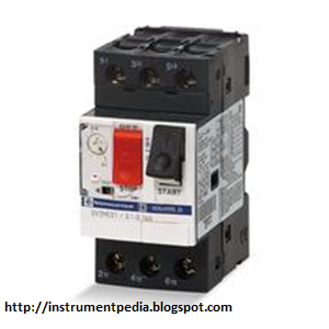
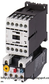
Over Load Relay
|
|
|
|
 |
|
 |
|
 |
 |
|
|
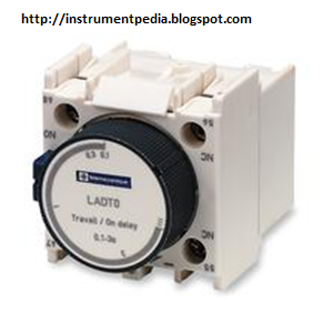
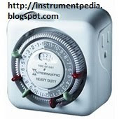
| Timer |
|
|
|
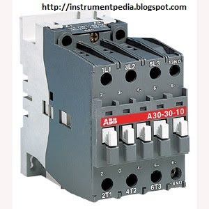
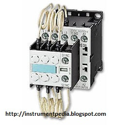
Contector
|
|
|
|
 |
|
|
|
 |
 |
|
|
Configurations can be provided to suit your application, these may include, steel wall mounting enclosure with bottom, and/or top cable entry. Steel floor standing enclosures, mounted within galvanised crash frames. Other enclosure materials are available including rigid rubber and HDPE.
3 or 4 Pole switching from 16Amp to 2500Amp, up to 400Vac. (AC21/22A) – [11 to 1700 kVA].
Automatically switches your load to a backup supply in the event of a mains supply failure.
Automatic Mains Failure systems are electrical control panels designed to keep your electrical equipment, (the load), running from a secondary electrical supply should your primary electrical supply fail.
The primary supply, (usually a mains supply), can be monitored for phase failure, under voltage, phase imbalance, phase rotation and neutral shift. Should there be a problem with the primary supply, the AMF panel will signal that the secondary supply, (usually a generator), is required.
This secondary supply is also monitored, and when healthy, switched to feed the load.
Rotary motorised switch with centre off position, to enable automatic selection of 2 different supplies. Most commonly a mains supply and a back-up generator supply.
Utilising the same range of switches as our MCO range, these are equipped with motor operators and a programmable electronic control module to monitor the condition of both supplies and provide signalling to stand-by supply or generator as required.
3 or 4 Pole switching from 160 to 1600Amp, up to 400Vac. (AC21/22A) – [110 to 1000 kVA].
Can be electronically motorised in the form of Deep Sea and OTM control units.
As with other changeover systems, a range of enclosure options are available and we are happy to engineer specific application solutions.
A range of cost effective, value for money automatic transfer control panels, to enable selection of 2 different supplies. Most commonly a mains supply and a back-up generator supply.
Just the mains or supply 1 is monitored, and should this supply fail the ATS will signal to start the generator or supply 2; when available this will be switched to the load.
Should the mains become healthy again, the Auto Transfer Switch will automatically switch back to utilise this supply.
Generally available in proprietary wall mounting steel enclosures painted to RAL7035, we are happy to offer engineered options including alternative enclosures, or control configurations, such as cool down timers.
Single phase or Three phase; 4 Pole contactor switching from 32 to 800Amp, (AC21/22A) [22 to 550 kVA – three phase].
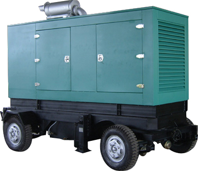
POWER ON RENT
We provide power on rent for a week, a month or longer. We can take care of your power needs. Our package comes complete with consumables, product support and operators.
PCSS provide the rental generator temporary power, emergency, and other rental industrial energy solutions.
SOLAR SYSTEM
PROBLEMS
In Pakistan, the cost of electrical energy from the grid is very high and its increasing on an average of 7% annually. Moreover its also not reliable as people have to face severe power outages throughout the year.
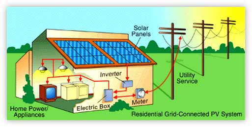
SOLUTION
Power Control Sales & Services provides such reliable solar energy solutions which can reduce electrical energy cost by 60% - 70%.
Power Control Sales & Services provides ON Grid and OFF Grid solar power systems, solar water pump systems for continuous and reliable electric power supply to the customers.
Power Control Sales & Services believes in high quality and standards and therefore supply only best quality products for solar power system from China, Spain and United States of America etc.
Power Control Sales & Services also provides design services to ensure that the solar power system always works at its optimum capacity and hence reduce both power demand and system cost to minimum.
Alongwith conventional solar power system, Power Control Sales & Services also provides innovative solar energy solutions like solar street lights, domestic solar lamps, fans and coolers etc.
PRODUCTS AND SERVICES
Power Control Sales & Services import its solar products from three globally acknowledged manufacturers around the world i.e. HUAYANG China, Zytech Spain and Solaropia USA as shown in the picture below.
We mainly categorize our products into 5 main categories which are as follows:

Solar power system products
Solar water pump system products
Solar water heater system products
Solar lighting products
Solar domestic products
Power Control Sales & Services has professional team to provide following services to its clients
Installation of Solar power system, Solar water pump system, Solar water heater system
Designing of ON Grid, OFF Grid and Hybrid solar power system, DC, AC and Hybric submersible solar water pump system etc.
Regular maintenance of the installed solar systems.